The resistance of conductors changes with change in temperature. This behavior is used for temperature measurement in RTDs. RTDs show Positive Temperature Coefficient (PTC) of resistance as their resistance increases with the increase in temperature. Metals like platinum, nickel and copper are commonly used as RTDs in industry. Platinum is used widely because its resistance characteristic remains stable over a wide range of temperature. Also its resistivity is very high, so less material is required for the construction of RTD. RTDs are useful for temperature range:
– 200 °C to + 650 °C
The relation between the resistance of RTD and the temperature is given by,
RT = R0 (1 + αT + βT2)
where, RT = Resistance of RTD at temperature T°C.
R0 = Resistance of RTD at 0°C.
α, β = Temperature coefficient of resistance of the material used for RTD.
T = Change in temperature
Construction of Resistance Temperature Detector (RTD)
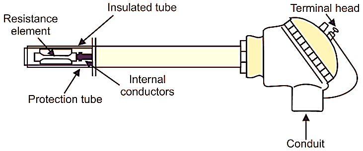
Fig. 1: Construction of RTD
Fig. 1 shows the construction of RTD. It consists of a resistance element, internal conductors, insulated tube, protection tube, reinforcing tube and a terminal head.
Resistance Element: An RTD uses platinum, nickel or copper as the resistance element. Usually, the resistance element is constructed by winding a platinum wire on a glass bobbin as a bifilar with a stainless steel fin. It is placed in a protection tube to provide excellent resistance against vibration.
Internal Lead Wire: It is used to connect the resistance element to the terminal. A standard nickel lead wire is generally used for this purpose.
Insulated Tube: It is used for insulating the internal lead wire. It also gives protection against a short circuit. For high temperature, a ceramic insulator is used and for medium temperatures a fiber glass is used.
Protection Tube: It protects the resistance element, internal lead wires etc. when operated in extreme ambient conditions. So the material used for it must be selected properly.
Terminal Head: It is used to connect the RTD to the external lead wire.
Advantages of RTD
- Fast response.
- High accuracy.
- Wide range of temperature measurement.
- Temperature compensation is not required.
- Good reproducibility and stability.
- Small in size.
Disadvantages of RTD
- The resistance of RTD may change due to self heating.
- Require a bridge circuit and external power supply for measurement.
- High cost