Q Meter equipment is basically meant for measuring the quality factor or circuit magnification factor of coils. Apart from this, it is also used to measure the self-capacitance of RF coils, capacitance of small capacitors. Fig. 1 shows the pictorial view of a Q-meter.
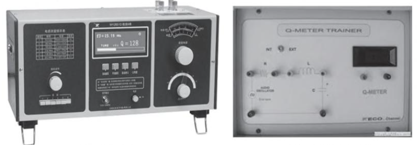
Figure 1: Q Meter.
Circuit Diagram & Working Principle of Q Meter
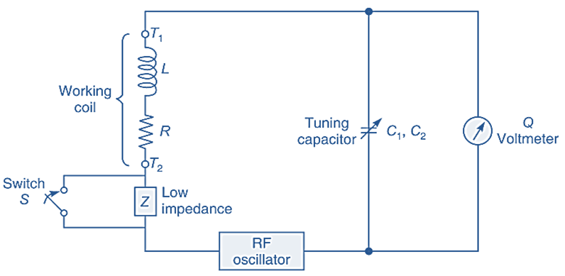
Fig. 2: Q Meter Series Connection Circuit Diagram.
Fig. 2 depicts the basic principle of operation of a Q-meter. The circuit comprises of two main sections (a) signal generator section and (b) electronic voltmeter. In addition to this, it incorporates two tuning capacitors and a thermocouple high frequency current meter.
The RF signal generator section generates a signal of a desired frequency within a frequency range of 50 kHz to 70 MHz. This frequency range is usually covered in five to six ranges. The signal output voltage of the signal generator is adjusted by means of a potentiometer provided for this purpose. The signal passes a current through a standard resistor (r) and this current is measured by means a thermocouple meter. The signal current is adjusted so that an RF signal of 1 volt develops across the standard resistor. This signal is fed as input to the test circuit.
The coil under test along with the two tuning capacitors form a series circuit and it is tuned to the signal frequency with the adjustment of the two tuning capacitors. The voltage across the tuning capacitors is measured by the electronic voltmeter. Circuit tuning is indicated by maximum reading in the electronic voltmeter.
Q of a coil has been defined as the ratio of the voltage across L or C to the input voltage
\[Q=\frac{{{v}_{C}}\text{ or }{{\text{v}}_{\text{L}}}}{v}\]
Since vC has been measured by electronic voltmeter and since input signal voltage has been fixed at 1 volt (i.e. v = 1V), Q is given as,
\[Q=\frac{{{v}_{C}}}{v}={{v}_{C}}\]
Thus the reading obtained in the electronic voltmeter gives a direct indication of the quality factor of the coil under test. If the quality factor of the coil under test is high, then input signal voltage is reduced to 0.1 volt so that the Q factor is 10 times the reading obtained at the voltmeter.
The instrument has an accuracy of about ± 5% for Q measurement upto 15 MHz. In addition of Q measurements, self inductance of a coil may also be determined but no direct scale for this purpose is available. Once the circuit with unknown inductance has been tuned, the signal frequency and tuning capacitance is noted down and value of coil inductance is computed from the relation
\[f=\frac{1}{2\pi \sqrt{LC}}\]
It is also possible to measure unknown capacitance of small capacitors with this instrument. For this purpose a standard inductor is used and the circuit is tuned with tuning capacitor. Now the unknown capacitor is connected in the circuit and tuning capacitor is retuned to obtain maximum reading in the voltmeter. Since the unknown capacitor has been connected in parallel with the tuning capacitor, the decrease in the capacitance of the tuning capacitor has to be made to obtain resonance after unknown capacitance is connected and this equals the value of unknown capacitance.