An ideal transformer is the transformer having the following Properties.
- The losses are zero (No iron loss, no copper loss).
- The primary and secondary winding resistances are zero.
- The leakage flux is zero. Therefore all the flux produced by the primary winding is coupled to the secondary.
- A small current is required to develop flux inside the core. This happens because the permeability of the core is very large.
- The external voltage applied to the primary, V1 is same as the primary induced voltage El. This is because the primary winding resistance is zero and so there is no voltage drop across it.
\[{{E}_{1}}={{V}_{1}}\]
- Similarly the voltage induced in the secondary winding (E2) will be equal to the load voltage V2, because the secondary resistance is zero.
\[{{E}_{2}}={{V}_{2}}\]
8. The transformation ratio for an ideal transformer is given by
\[k=\frac{{{E}_{2}}}{{{E}_{1}}}=\frac{{{V}_{2}}}{{{V}_{1}}}\]
- Efficiency of an ideal transformer is 100%. This is because there are no losses taking place.
- The voltage regulation is That means the secondary voltage will remain constant irrespective of the load current.
Ideal Transformer on No Load of Ideal Transformer
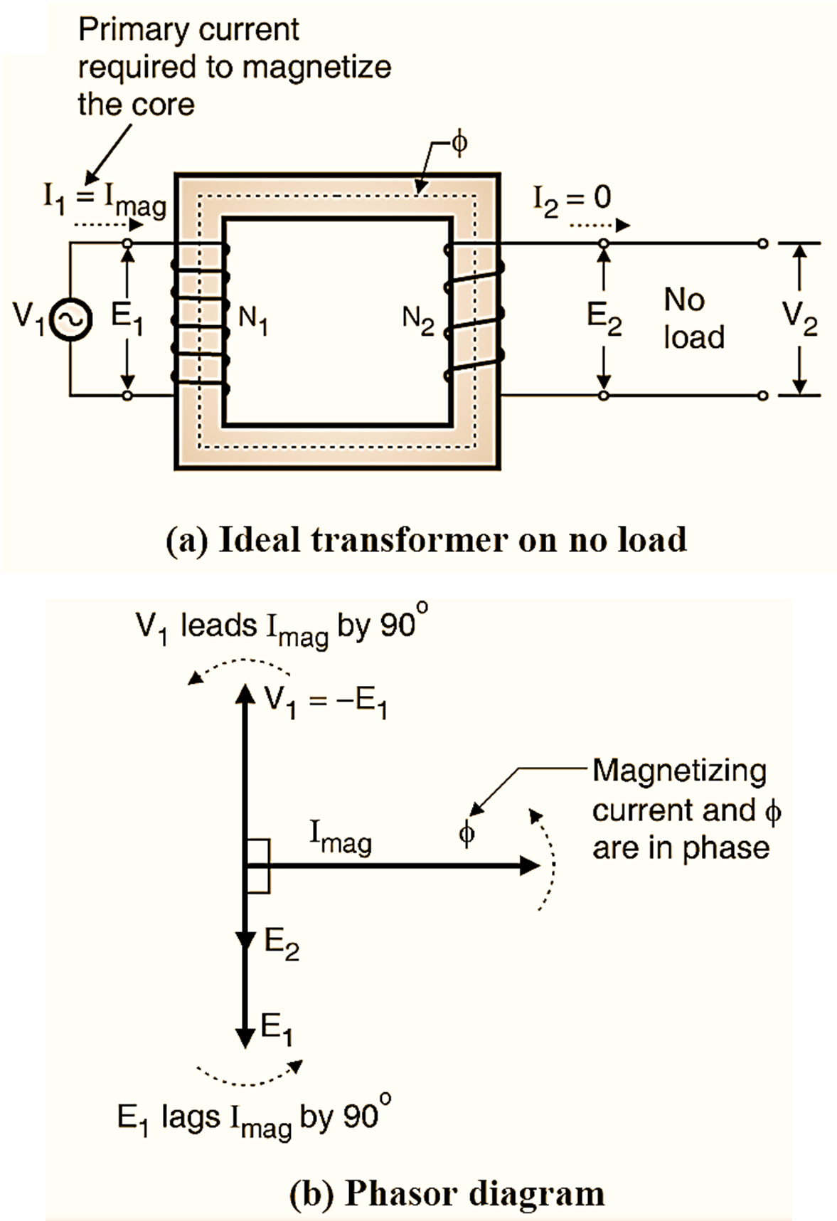
Figure 1: Ideal Transformer.
An ideal transformer is as shown in Fig. 1(a). An ideal transformer is the one which has no power losses. In order to have a transformer with zero loss, the following conditions should be satisfied.
Conditions for an ideal or loss free transformer:
- The transformer primary & secondary winding resistance should be zero.
- The hysteresis loss and eddy current loss should be zero.
- There should not be any leakage flux.
Operation and Phasor Diagram of an Ideal Transformer
An ac voltage V1 is applied across the primary winding of the transformer (see Figure 1(a)). As the load on the transformer is zero i.e. RL ideally the primary current I1 = 0. But practically a small current called the magnetizing current Im flows through the primary winding. The magnetizing current is used by the transformer for magnetizing the transformer core. As the primary winding is assumed to be purely reactive (R = 0) the magnetizing current lags behind the primary induced voltage by 90º as shown in Fig. 1(b). Due to the sinusoidal magnetizing current, a sinusoidal varying magnetic flux is produced in the iron core. This flux is in phase with Im as shown in Fig. 1(b). Due to this varying flux, emfs are induced in the primary (self-induced voltage) El and secondary (mutually induced voltage) E2 respectively.
\[{{E}_{1}}=-{{V}_{1}}\text{ and }{{E}_{2}}={{V}_{2}}\]
The magnitudes of E1 and E2 are proportional to the number of tums N1 and N2 respectively. The secondary induced voltage E2 will also oppose V1. So E2 also appears 180º out of phase with V1. The magnitude of E2 however is dependent on the turns ratio N2/N1. E1 and E2 appear in phase with each other and 180º out of phase with V1.
Power input on no load:
The input power to the ideal transformer on no load is given by,
\[{{P}_{0}}={{V}_{1}}{{I}_{m}}\cos {{\phi }_{0}}\]
Where,
\[\begin{align}
& {{\phi }_{0}}=\text{ Angle between }{{\text{V}}_{1}}\text{ and }{{\text{I}}_{m}}\text{ which is 90}{}^\circ \\
& \\
\end{align}\]
Thus the input power to an ideal transformer on no load is zero. The output power is zero and there are no losses taking place in the ideal transformer.
Ideal Transformer on Load
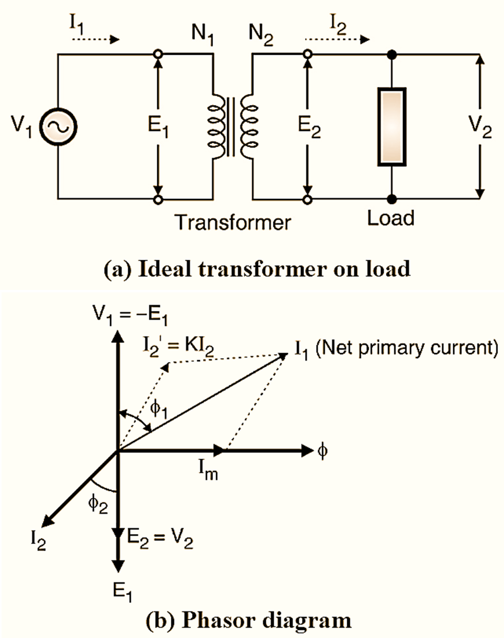
Figure 2: Ideal Transformer on load.
When some load is connected between the secondary terminals of the transformer it is said that the transformer is loaded or it is on load. Due to the load on the secondary, a finite secondary current (I2) starts flowing. If the load is (R + L) type then I2 will lag behind V2 by an angle as shown in Fig. 2(b). As per the Lenz’s law, the secondary current I2 will oppose the cause producing it. Hence it opposes the magnetic flux. This is called as demagnetizing effect of I2. Due to demagnetizing, the flux is weakened and it reduces the amount of self-induced voltage El. Due to reduction in El, the difference between V1 and El will increase and the additional primary current I’2 called as load component starts flowing as shown in Fig. 2(b).
\[{{{{I}’}}_{2}}={{I}_{2}}\times \frac{{{N}_{2}}}{{{N}_{1}}}=K{{I}_{2}}\]
The current I’2 = KI2 and it is 180º out of phase with the current I2. The net primary current I1 is the phasor sum of I’2 and Im as shown in Fig. 2(b).
\[{{\overline{I}_{2}}}={{{\overline{{I}’}}_{m}}}+{{I}_{m}}\]
Thus due to load on secondary side, the primary current of the transformer increases to supply the additional power to the load. The angle between V1 and I1 is ϕ1 as shown in Fig. 2(b).
Why does primary current increase when the load current is increased ?
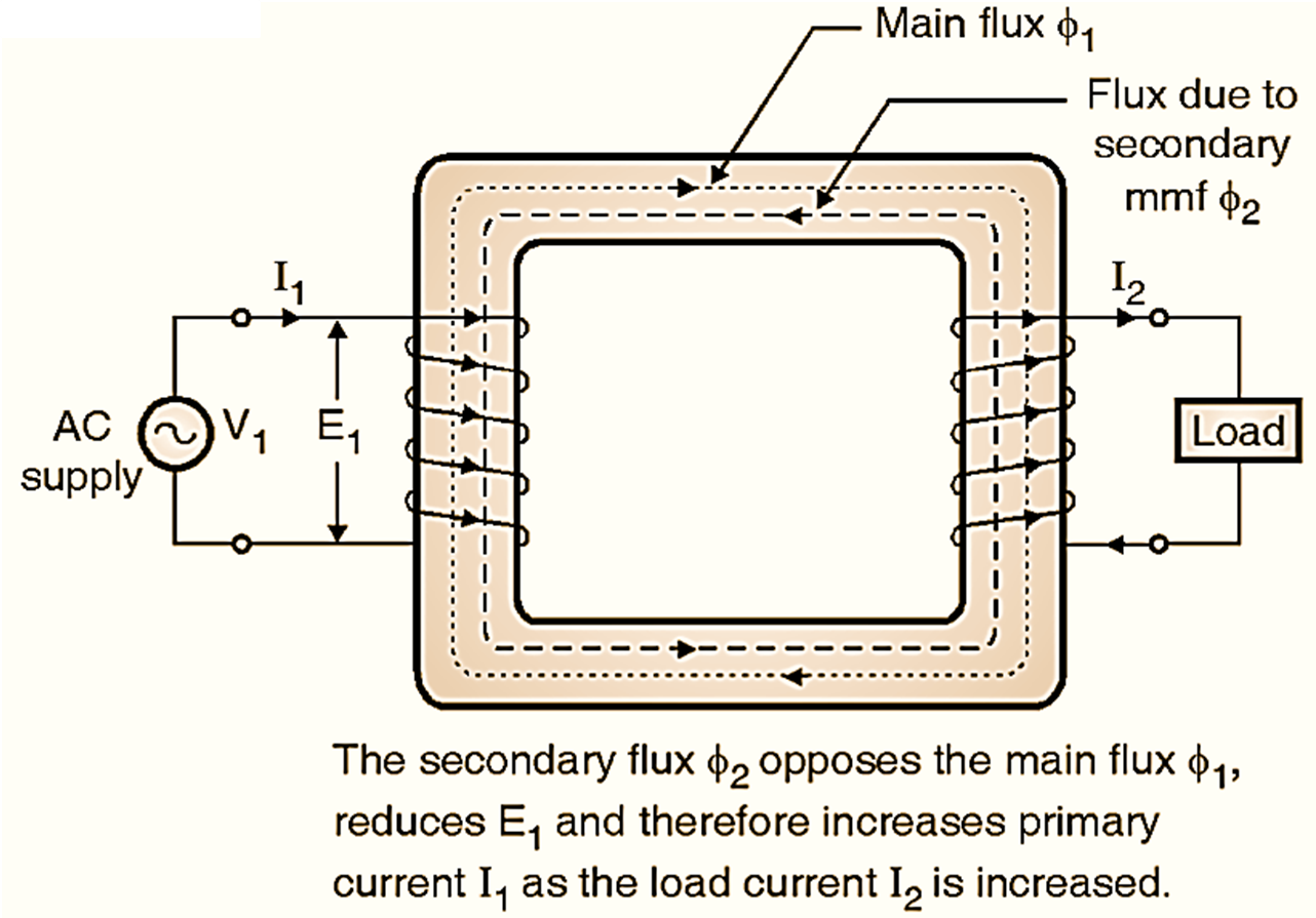
When the transformer is loaded, the load current I2 will start flowing. Due to increase in load current I2 the secondary ampere tums N2I2 will increase. This increased secondary mmf (N2I2) will increase the flux set up by the secondary current. This flux opposes the main flux ϕ1 set up in the core by the current flowing through the primary winding. Hence the secondary mmf N2I2 is called as the demagnetizing ampere. Due to reduction in the main flux ϕ1, the induced emf in the primary winding E1 will also reduce. Hence the difference between V1 and El will increase and the primary current will Increase and the primary power factor is ϕ1.