The function generator is versatile instrument that gives a number of different waveforms at the output with their frequencies that can be adjusted over a wide range.
The most commonly used output waveforms are the sine wave, square wave, triangular wave and saw-tooth wave with frequencies that can be adjusted from fraction of a hertz to several hundred kilohertz. Different output signals from the function generator may be available simultaneously. Another useful feature of the function generator is to phase lock to an external signal source. A function generator may be used to phase lock another function generator and the two output signals may be displaced in phase according to a requirement. The function generator may be phase locked to a frequency standard. The function generator outputs will then have the same frequency accuracy and stability as the frequency standard.
Block Diagram of Function Generator
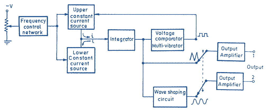
Fig. 1: Block Diagram of a Function Generator.
Fig. 1 shows the block diagram of a function generator. The circuit does not employ a conventional oscillator circuit because these oscillators fail to operate at very low frequencies. It uses a different technique for generating signals. Here two constant current sources are used to feed the integrator circuit. When the circuit is switched on, the upper constant current source sends a constant current into the integrator and the output of the integrator starts rising linearly depending upon the magnitude of the constant current supplied by the upper current source. The integrator output is connected to the comparator. When integrator output reaches a pre-determined level, the comparator changes state; the upper constant current source is cut-off while the lower current source is switched on. This current source passes a current in reverse direction and the voltage at the integrator output starts decreasing linearly. When this output decreases to a pre-determined level, the comparator again switches on. The lower current source is switched off and upper current source is switched on and the circuit repeats the same action.
The rate of rise/fall of the integrator output depends upon the magnitude of the current supplied by the upper / flower constant current sources. Changing the magnitudes of these currents would, therefore, change the frequency of the integrator output. The frequency control network controls the magnitudes of current sources and hence the frequency of the output. For this reason, this network is termed as the frequency control network.
The integrator output is of triangular waveform. The waveform may be amplified by an output amplifier and obtained at the output.
The comparator output which is used to switch over function of the current sources is of square wave-shape. This square wave output may be amplified and used as a square wave output.
Lastly, the triangular wave produced by the integrator is given to resistance-diode wave-shaping circuit which converts this triangular signal into a sinusoidal signal.
There are two selector switches S1 and S2. S1 decides the input signal given to output amplifier 1 and S2 gives the input signal to amplifier 2. We may obtain any two waves in the output by putting these switches in the appropriate positions.