A dial gauge, also known as a dial indicator, is a precision measuring instrument used to measure small linear distances with high accuracy. It is widely used in mechanical engineering and manufacturing for measuring flatness, alignment, and deflections in machine components.
Key Features of Dial Gauge:
- Measures small displacements in micrometers (µm).
- Uses a dial with a pointer for easy reading.
- Works on the principle of mechanical magnification.
Parts of a Dial Gauge
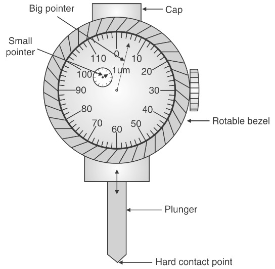
The dial gauge consists of several components, as shown in the diagram provided.
Main Parts:
- Dial Face: The circular scale where measurements are displayed.
- Big Pointer: Indicates the main measurement reading.
- Small Pointer (Revolution Counter): Records the number of rotations of the big pointer.
- Plunger (Spindle/Probe): The contact point that moves to detect surface variations.
- Hard Contact Point: The tip of the plunger that touches the surface.
- Rotatable Bezel: Allows for setting the zero reference point.
- Gears & Levers: Transmit motion from the plunger to the dial.
- Cap & Body: The casing that houses the internal mechanisms.
Working Principle of Dial Gauge
The working principle of a dial gauge is based on mechanical amplification. The movement of the plunger (contact point) is transferred to the gears and levers inside the gauge, which amplifies the small movement and displays it on a circular graduated dial.
Working of a Dial Gauge (Dial Indicator)
A dial gauge works on the principle of mechanical magnification, where small linear displacements of the plunger are converted into amplified rotational motion, which is displayed on a calibrated dial.
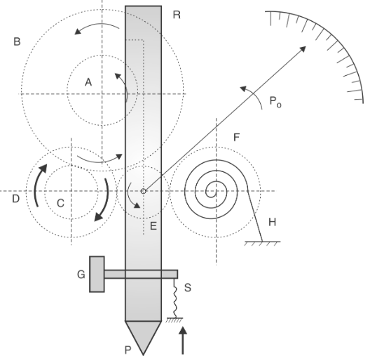
Step-by-Step Working Process:
- Contact with the Surface: The plunger (P) is placed against the surface to be measured. Any variation in surface height causes the plunger to move up or down.
- Transmission of Movement: The vertical movement of the plunger is transmitted to the rack-and-pinion (E) mechanism. The rack (R) moves up and down, rotating the pinion (A).
- Gear Train & Mechanical Amplification: The rotation of the pinion (A) is transmitted through a gear train (B, C, D). Each gear increases the angular displacement, amplifying the motion.
- Needle Movement on Dial: The amplified motion is transmitted to the pointer (Po) via a spiral spring (F). The pointer moves on a graduated dial to display the measurement.
- Zero Setting & Measurement: The rotatable bezel (G) allows the user to set the zero reference point. The spring (S) ensures that the plunger maintains constant contact with the surface.
Summary of Step-by-Step Working Process:
- The plunger (probe) of the gauge is placed in contact with the surface to be measured.
- Any displacement causes the plunger to move up or down.
- This movement is transferred through rack and pinion gears to the rotating pointer.
- The pointer moves on a calibrated dial, indicating the measurement.
Least Count of a Dial Gauge
The least count of a dial gauge refers to the smallest measurement it can accurately display.
Formula to Calculate Least Count:
\[
\text{Least Count} = \frac{\text{Smallest Division on Dial}}{\text{Number of Divisions per Revolution}}
\]
Standard Least Counts:
- 0.01 mm (10 µm)
- 0.001 mm (1 µm)
- High-precision gauges can measure up to 0.0001 mm (0.1 µm).
Types of Dial Gauges
| Type | Description | Application |
|---|---|---|
| Plunger Type Dial Gauge | Has a vertical plunger for measurement. | Used for general surface measurements. |
| Lever Type Dial Gauge | Uses a pivoted lever instead of a plunger. | Measures small deflections and angles. |
| Continuous Dial Gauge | Displays continuous readings without interruption. | Used for dynamic measurements. |
| Reversed Dial Gauge | Has reversed numbering for specialized uses. | Ideal for unique orientations in machining. |
| Mechanical Dial Indicator | Uses only mechanical gears for measurement. | Traditional applications in machining and quality control. |
| Electronic Dial Indicator | Digital display with electronic sensors. | Used for high-precision and automated systems. |
| Magnetic Base Dial Indicator | Mounted on a magnetic stand for stability. | Used in machine tool alignment. |
| Back Plunger Dial Indicator | Designed with a rear-mounted plunger. | Used in narrow spaces and special fixtures. |
Advantages of Dial Gauge
Dial indicators are preferred due to their accuracy, ease of use, and versatility.
- High Precision – Measures minute displacements up to 1 µm.
- Easy to Read – The dial display provides a clear measurement.
- Durable & Reliable – Made from stainless steel for long-term use.
- No Power Required – Mechanical dial gauges do not require electricity.
- Wide Application Range – Used in manufacturing, metrology, and quality control.
Applications of Dial Gauge
Dial gauges are widely used in engineering, machining, and quality inspection.
- Surface Flatness Measurement: Ensures machine parts are level.
- Machine Tool Alignment: Used in lathe and milling machines.
- Gear and Bearing Measurement: Detects wear and misalignment.
- Automotive Industry: Checks cylinder bore and valve clearance.
- Railway Track Inspection: Measures track alignment and deviation.
Disadvantages of Dial Gauge
Despite its advantages, dial gauges have some limitations.
Fragile Mechanism – Internal gears can get damaged easily.
Limited Measurement Range – Typically 1-50 mm only.
Manual Zero Setting Required – Needs frequent recalibration.
Sensitive to Temperature – Thermal expansion can affect readings.
Conclusion
A dial gauge (dial indicator) is an essential precision measuring tool used in engineering, machining, and quality inspection. It works on the principle of mechanical amplification and provides highly accurate measurements. Despite some limitations, it remains a crucial instrument in industrial and laboratory applications.