An audio signal generator is a laboratory instrument that is commonly used for testing of Audio circuits.
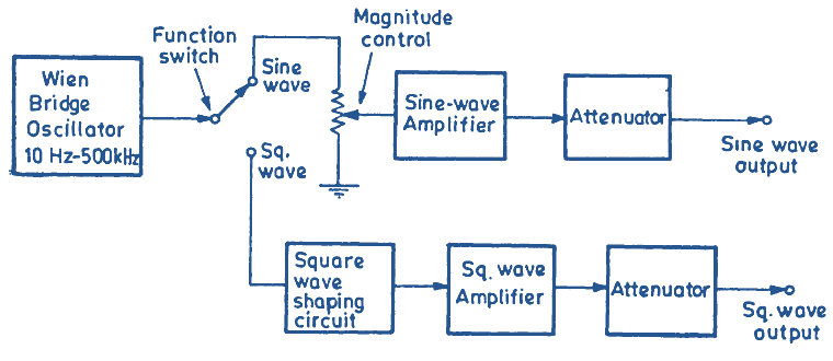
Fig. 1: Block Diagram of an Audio Signal Generator.
Block Diagram of Audio Signal Generator
Fig. 1 gives this block diagram of an audio oscillator that is capable of giving sinusoidal as well as square wave output. The Wein bridge oscillator is heart of the instrument and is used to generate sine-wave signal of any desired frequency with in a frequency range of 10 Hz – 500 kHz. The frequency of the oscillator is changed by means of a Range Switch and within a given range, frequency is made continuously variable.
The output of this oscillator is applied to sine wave circuit or a square wave circuit with the help of function switch. In the sine-wave mode, the signal is amplified and given to the output terminal through the attenuator. The amplitude can be set to any desired value by means of attenuator and the magnitude control.
When the function switch is in square-wave position, the oscillator output is given to a wave shaping circuit that converts the sinusoidal signal into square wave signal. The square wave signal in amplified and through an attenuator given to the output terminals. The attenuator is used for varying the amplitude of the square wave output. Fig. 2 shows an audio signal generator used in laboratories.