A dynamometer is a device used to measure torque absorbed or torque transmitted by rotating member. It helps to determine power produced or absorbed or delivered by rotating shaft.
Types of Dynamometer
Dynamometers can be broadly classified into two types. They are :
- Absorption Dynamometers
- Transmission Dynamometers
1. Absorption Dynamometers
Absorption dynamometers measures the power output of the engine to which they are coupled by absorption. The power absorbed is usually dissipated as heat by some medium. Example is Eddy current dynamometer.
2. Transmission Dynamometers
In transmission dynamometers the power is measured by transmission principle which is transferred to the load coupled to the engine and then it is indicated on indicator . These are also called torque meters. Example is strain gauge transmission dynamometer.
Eddy current Dynamometer

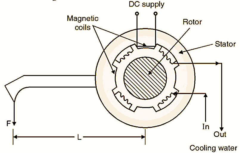
Fig. 1: Eddy current dynamometer.
Eddy current is the type of absorption type dynamometer. It consists of non-magnetic solid metallic rotor, which moves in the magnetic field of stator. The stator winding is excited by a D.C. supply as shown in Fig. l. When the solid rotor moves in the field produced by stator windings an emf is produced in it resulting in a large loss of power due to eddy current. This power is dissipated as heat in the rotor and therefore water is circulated through air gap between stator and rotor. Torque on the stator casing may be measured in the usual manner.
Eddy current Dynamometer Advantages
- They are small in size, as compare to any other of the same capacity.
- The absorption power can be changed by changing d.c. circuit.
- It can measure high power output at all speeds.
- Torque developed is smooth and continuous under all operating conditions.
- The power range of eddy current brake is up to 300 h.p. and maximum speed is 6000 rpm.
Eddy current Dynamometer Limitations
- It cannot produce any torque at zero speed.
- It produces only small torques at low speed.
Strain Gauge Transmission Dynamometer
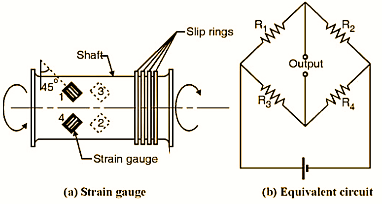
This is also inline rotating torque sensor, which measures torque. Fig. 2 shows the arrangement of strain gauge dynamometer.

Fig. 1: Strain Gauge Transmission dynamometer.
Strain Gauge Transmission Dynamometer Construction and Measurement
It consists of metal shaft fitted with bonded strain gauge. Here strain gauges are fitted at 45º to shaft axis as shown in Fig. 2.6.2(a). In this type of arrangement 2 strain gauges are subjected to tensile stress and while other is subjected to compressive stress. Strain gauge 1 and 3 must be diametrically opposite to strain gauge 2 and 4. Due to torsion, strain gauge senses compressive as well as tensile deformation. Further these strain gauges are connected to Wheatstone circuit. The output of Wheatstone bridge is proportional to torsion and hence to applied torque on shaft. The bridge power and output of bridge is connected to the sensor through slip ring and brushes as shown in Fig. 2.6.2(b).
Strain Gauge Transmission Dynamometer Advantages
- It is sensitive to torque.
- It has full temperature compensation.
- It provides automatic compensation for bending and axial loads.
- It gives an instantaneous result.
Strain Gauge Transmission Dynamometer Disadvantages
- The slip rings may wear out and causes maintenance problems.
- The device is generally expensive.
- Initial settings need skill and is time consuming.
