The standard signal generator is a very useful instrument that is commonly used for testing and alignment of radio receivers.

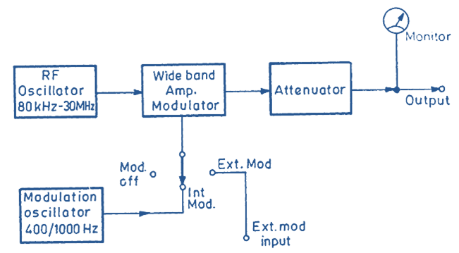
Fig. 1: Block Diagram of Standard Signal Generator.
Block Diagram of Standard Signal Generator
It is often used in the measurement of gain, signal to noise ratio, bandwidth, standing wave ratio and other circuit parameters.
The signal generator may be considered as a source of RF energy with a known frequency and amplitude. This energy may be a simple RF carrier or modulated to a required depth of modulation. Amplitude modulation is commonly used in standard signal generators because most of the radio receivers are AM receivers. Sinusoidal modulating signals are commonly used but sometimes the modulating signal may be of square wave or pulse type. The output voltage can be accurately adjusted by means of a calibrated attenuator and read by an output meter. Fig. 1 gives the block diagram of a standard signal generator.
The instrument consists of an RF oscillator that can give sinusoidal signals with a frequency that can be set anywhere in the range of 80 kHz to 30 MHz. This RF signal is given to the wideband amplifier which amplifies this signal. The amplified signal is given to the output terminals through a calibrated attenuator which is set to give RF output of the desired magnitude.
The instrument is provided with a modulation switch. When this switch is put in the OFF position the modulating signal is not connected and the output available is RF carrier. When this switch is put to INT. MOD position, AF signal from the Modulation Oscillator is applied to the wideband amplifier. This amplifier now works as a modulator and gives an Amplitude modulated RF signal to the output. The modulation oscillator usually operates at standard modulating signal frequencies of 400 Hz and 1000 Hz.
In the third position of the modulation switch, the internal modulation is cut-off and we can use external audio signal for modulation. By changing the amplitude of this A.F signal, we can change the depth of modulation. Frequency of modulating signal can also be varied. This is an important requirement when we are measuring the overall fidelity of a radio receiver.
The signal output can usually be adjusted within a range of 1 µV to 1 V in steps.
